E-Unit and Electronic E-Unit
All Lionel steam engines and diesel engines contain an E-unit. The E-unit gives the train operator control over the direction of travel simply by applying and removing track power.
During the postwar era, Lionel used two versions of E-units: a 2 position E-unit and a 3 position E-unit. The less common of the two, the 2 position E-unit has two states of operation: forward and reverse. The more common 3 position E-unit has three states of operation: forward, reverse, and idle. While the forward and reverse states are self explanatory, the idle state allows the operator to apply power to the track without moving the engine.
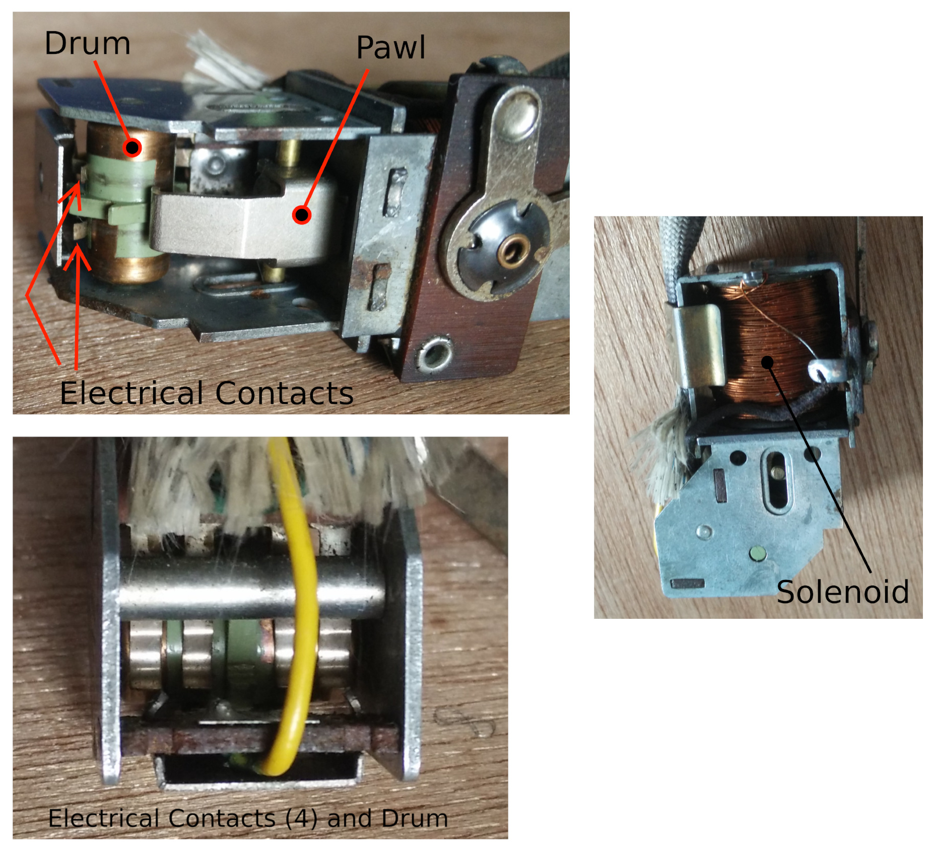
Occasionally referred to as a rotary sequence switch, the e-unit physically consists six electrical contacts, a rotating drum, a pawl, and a solenoid. Operationally every time the solenoid is activated, the pawl is pulled upwards rotating the drum. The solenoid returns to its original position by either a spring or gravity when power is removed from the track. The drum and the electrical contacts essentially behave like two single pole / triple throw switches. With this setup, the E-unit is able to have 3 powered states.
The behavioral differences of the two E-units are as follows:
2 Position E-Unit Behavior
| Transformer | Track Power | Solenoid | E-Unit State | Engine |
| Off | No | Down | “Reverse” | Stationary |
| On | Yes | Up | “Forward” | Forward |
| Off | No | Down | “Forward” | Stationary |
| On | Yes | Up | “Reverse” | Forward |
3 Position E-Unit Behavior
| Transformer | Track Power | Solenoid | E-Unit State | Engine |
| Off | No | Down | “Reverse” | Stationary |
| On | Yes | Up | “Idle” | Stationary |
| Off | No | Down | “Idle” | Stationary |
| On | Yes | Up | “Forward” | Forward |
| Off | No | Down | “Forward” | Stationary |
| On | Yes | Up | “Idle” | Stationary |
| Off | No | Down | “Idle” | Stationary |
| On | Yes | Up | “Reverse” | Reverse |
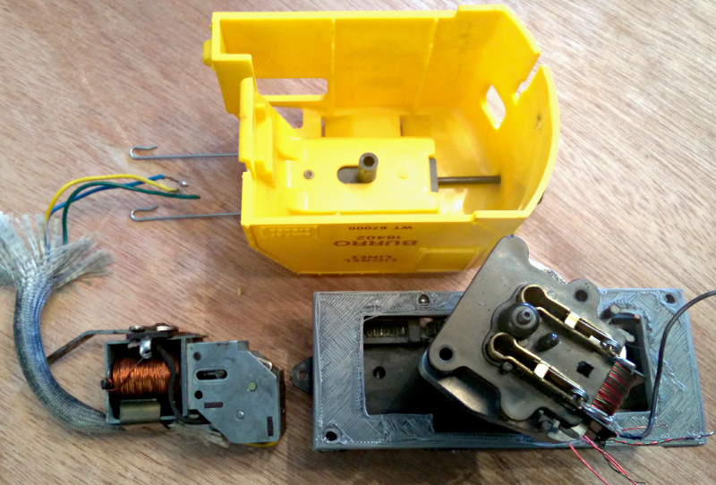
The stock Lionel E-unit is rather large and the space inside the Burro Crane is small – the majority of which is taken up by the stock motor. As a result, the plan is to design an electronic E-unit.
From a feature-set standpoint, the electronic E-unit will need to
1) detect when the power transformer is “off” and when the transformer is “on”
2) remember the current state of the E-unit
3) know the order of the states
4) know how to direct current to the motor in each state (forward, reverse, stationary)
Currently the plan is to use a microcontroller as the “brains” of the electronic E-unit. For the detection of the track power, I plan to use an optoisolator circuit. And for directing current to the burro motor, I plan to use an H-bridge integrated circuit.
Due to limited space within the Burro Crane cab, relays will not be the first choice for controlling the motor. I may attempt to use triacs. But my first attempt will employ an H-bridge integrated circuit. Note that with the H-bridge, the motor will be need to be controlled with direct current, not alternating current. Since the microcontroller will, also, need direct current, direct current will be available.
As far as being able to power the microcontroller when track power is “off” (which occurs when the operator is trying to reverse directions of the engine), the plan is to use a “Super” capacitor to store enough energy while track power is off and still run the microcontroller for a short period of time. If that does not work, I will likely revert to some type of battery technology like a standard watch battery or a perhaps a lithium ion battery.