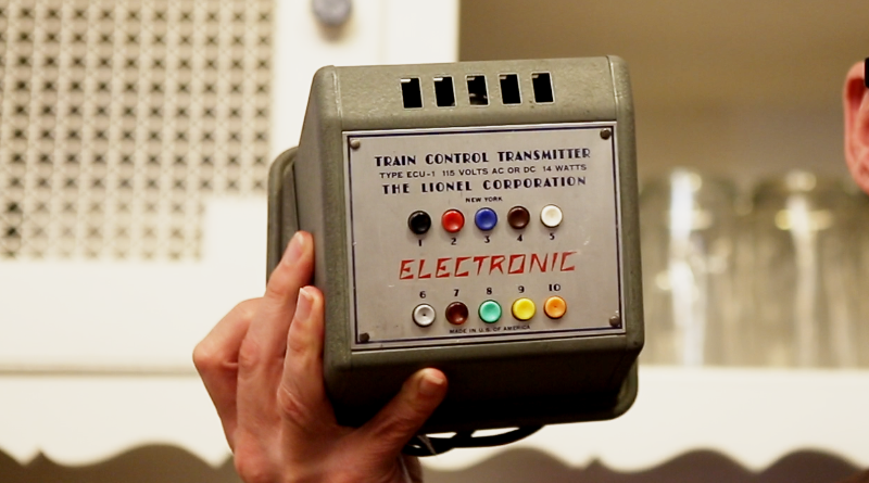
ECU-1 Transmitter
The ECU-1 transmitter along with the RU-1 receivers create the radio frequency link that allows the Electronic Set operator to control 10 different train-related actions on the layout without the need of a Remote Control Section of track. This design feature separated the Electronic Set apart from all other train sets created to that point in time.
The ECU-1 is designed with a 117N7GT (or alternatively a 117P7GT) rectifier-beam power amplifier vacuum tube. This vacuum tube integrated much of the design needed for the transmitter. Minimal circuitry surrounds the tube along with a pair of mutually coupled inductors providing both a necessary component for oscillation and a mechanism for coupling the output to the track power.
Operationally, the ECU-1 consists of 10 different channels that are each controlled by a push button on the front panel of the transmitter. Each channel oscillates at a different frequency within the range of 200kHz – 400kHz. The output for each is targeted to have an RMS amplitude of 3V.
Measurements for my ECU-1 are as follows:
| ECU-1 Button Number | Voltage, VRMS [V] | Frequency, f [kHz] | Ideal Frequency [kHz] |
| 1 | 3.3 | 357.1 | 352.2 |
| 2 | 3.1 | 322.6 | 318.3 |
| 3 | 3.1 | 294.1 | 289.5 |
| 4 | 3 | 270.3 | 263.3 |
| 5 | 3 | 238.1 | 239.5 |
| 6 | 3.3 | 344.8 | 333.8 |
| 7 | 3.1 | 303 | 302.6 |
| 8 | 3 | 277.8 | 276.2 |
| 9 | 3 | 250 | 251.1 |
| 10 | 2.7 | 227.3 | 228.3 |
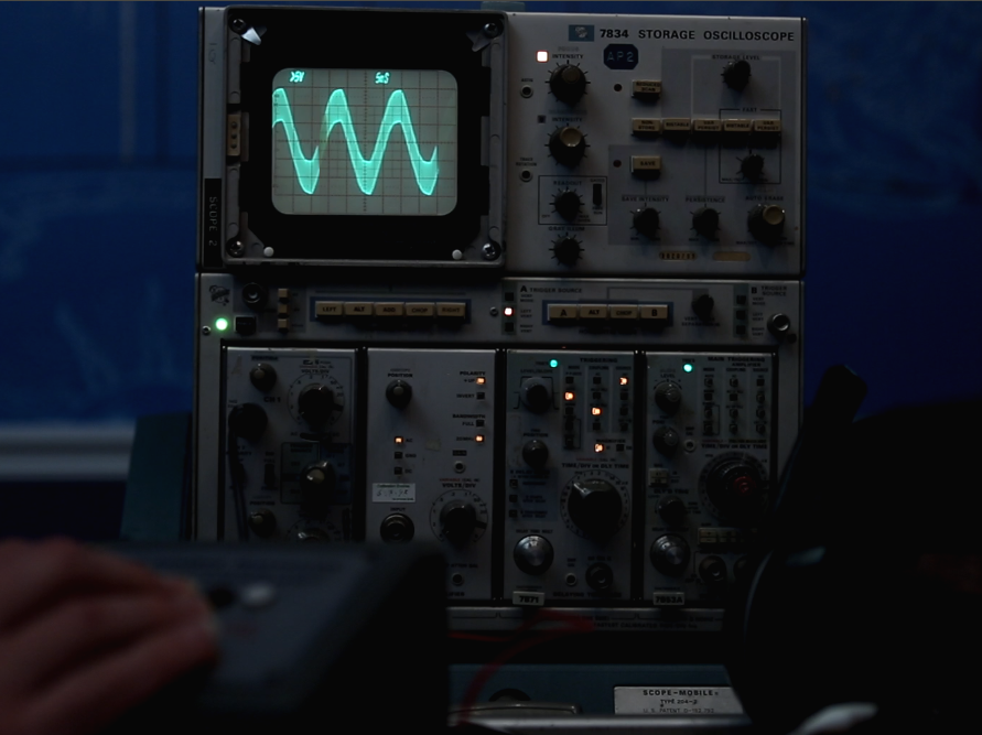
When tested with a ZW transformer, my ECU-1 appeared to work properly. The oscilloscope clearly displayed a high frequency signal superimposed upon a 60Hz track power signal.
The software that I am using for the real-time calculations is Octave. Octave is very similar to Matlab by the company Mathworks but does not require a license. The spreadsheet in which I’m recording the results is LibreOffice Calc from the LibreOffice Suite.